|
|
www.conserver.com |
|
|
www.conserver.com |
Beyond these three, there are some images and ramblings about an RJ-45 signal tracer that I'm cobbling together, and some artwork about using the signal tracer.
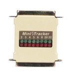
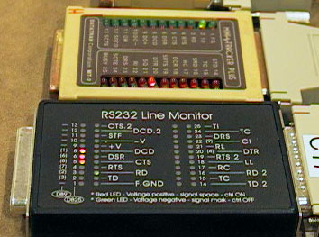
My DataTran signal tracers are a vital troubleshooting tool for me, and they have earned their place in my Doctor Bag. I wish they were still in business, so that they could make these RJ-45 tracers! (I wish I could find permission (and the plastic case molds) to make more of their DE-9 and DB-25 tracers...)
You can get more basic serial clues from my Minor Scroll of Console Knowledge (http://www.conserver.com/consoles/msock.html)
|
Looking at some definitions for the words Passive Signal Tracer;
This is a device, meant for looking at RS-232 signal levels. Because there are no batteries, the power for the display is derived from the signal leads. One benefit of this, is that you can usually see a low-voltage condition, which could be one cause for communications problems. However, drawing power from the signal leads can cause a drop in the signal voltages, so you cannot use these devices in the 'fringe cases'. (If your signal path is at the limits of length, or drive power, you may see a degradation of data when you insert a signal tracer.) Because they don't have batteries, a passive signal tracer is usually smaller and lighter than a Break-Out Box. Because there are no active components, these devices don't have the intelligence to monitor the data on the wire. A passive signal tracer is NOT a serial protocol analyzer, or a serial data tap device. Because a passive signal tracer does not emit a signal, it is NOT a cable tracer, or a cable analyzer. The signals (voltage levels) for RS-232 are different from the signals for Ethernet, Token Ring, and most other data interchange interfaces, so a passive signal tracer is NOT an Ethernet Link Checker. When you are following a cable through a 'rats nest', under a data center floor, or across a hanging ceiling, sometimes you can make a mistake, and wind up following the wrong cable. When you get to the "other end", a passive signal tracer will let you see if you've still got an RS-232 signal, and with some simple testing, you can determine if this is the cable that you think it is.
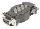
A breakout box is a device that lets you view the logic state of many, or all, of the signal leads, as well as providing some ability to interrupt some (or all) of the signal leads. Sometimes these devices need batteries to function. The access to the signal leads allows you to pass-through, disconnect, or cross-connect leads from one connector to another with jumper wires. The intention of a breakout box is to allow you to monitor the signals, and also simulate the adapter or cable that you need. However, I often find that breakout boxes are often left in service, rather than being replaced by the appropriate adapter(s) or custom cable. If the breakout box is allowed to hang freely, the weight of the breakout box can cause damage to the pins on the connectors (of the breakout box and the equipment it is hanging from), leading to reliability problems later on. One Breakout Box that I like is available from Benedict Communications. The BOB-100 is a low-profile device, and the LEDs and switches lie below the surface of the device. It has the ability to use an external 9-volt battery to provide +/- signals to stimulate signal leads, but you don't need to have the battery for most funtions. The unit also can test Current Loop interfaces! While I also like the ability to use the triggers (found on the BOB-100 Deluxe), but the larger size outweighed my occassional need for a trap. However, it's still a much nicer package than most that I've worked with to date. I prefer the Passive Signal Tracer. It is much smaller, and cheaper, than a Breakout Box, and I find that the signal tracer tells me all I need to know to establish the physical RS-232 link on DB-25 and DB-9 connections. It gives me a good clue if I have a reasonable cable, or (if the signals appear on strange pins) whether the cable may be wired strangely. It can tell me if an RJ-45 to DB-25 adapter is DTE or DCE, or (if the signals appear on strange pins) maybe the adapter isn't built with the RJ-45 wiring that I need. |
|
While the signal tracer won't automatically make the connection work if I have the wrong cable or adapter in place, it does gives me a quick, visual indication that I have the right or wrong parts. The signal tracer lets me see what "normal", working circuits look like, which lets me spot the abnormal conditions when they occur. The lights are the clues to what isn't right, and they tell me what to check next to resolve the interface conflict. If you are trying to connect two devices, your main clues lie with pins 2 & 3 on the DB-25 and DE-9 connectors. It really doesn't matter which pins are used to transmit and receive. The secret is knowing which pin is the transmitter from each device, and which is the receiver. The signal monitor will tell you this.(This is because you will need to tie the transmitter on one device to the receiver of the other device in order for traffic to pass, right?) There is a good description of how to select a pair of RJ-45 to DB-type connectors to connect two serial ports on the Minor Scroll page, as well as showing how to use a passive signal tracer to confirm that the connectors were the correct choice. |
The animated image below will show you how you can use a Passive Signal Tracer to connect to a serial port to check whether the transmit data is on pin 2 or pin 3, and then check the cable to see if you have the correct adapter (by looking for transmit data on the cable, before you try to connect the cables).

You can insert a passive signal tracer into a working serial connection, and watch the signals while the connection is working. The tracer can show you what "normal" looks like. Does the handshaking leads change state? Is the flow control ever invoked? How 'regular' or how 'bursty' is the data? Is it more in one direction than the other? Troubleshooting a system is easier when you know what the signals look like when the system is working.
When you are trying to troubleshoot a connection, you usually need to start with an understanding of how the physical connection is made, and what signals are connected. If you already have an idea how the connection is built, you can use the signal tracer to confirm what you already know. (Sometimes, the tracer will show you that the connection is NOT built the way you expected! Maybe you were wrong, or maybe someone changed it after you knew how it was built...but the tracer can show you how it is built NOW.)
If you don't know how the connection is built, you can use the signal tracer to find out. By inserting the passive signal tracer in the connection path at various points, you can determine if there is a wiring problem, and locate the failure between two connectors.
While a passive signal tracer doesn't allow you to make a special connection (like a Break-out Box would), it will show you what signals are present, so you can decide if the connection will work.
|
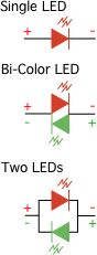
Look for a tracer that uses two separate LEDs for each signal lead This is a personal preference, I admit, but it comes from practical needs. Primarily, you have three signal conditions that you need to monitor (no signal, positive voltage, and negative voltage, in reference to the signal reference ground). You cannot do that with a single LED, as shown in the illustration at the right.
A Bi-Color LED has two LED elements in the same device, biased in opposite directions. You pick which LED will light based on the polarity of the power applied. With this device, RED indicates one polarity, and GREEN indicates the other, while a dark LED indicates no signal at all. (A 'yellow' or 'orange' color indicates that the polarity is alternating rapidly.) Back in the 300-2400 bits-per-second data days, it was easy enough to notice when a bi-color LED was in a steady red or green, and when it was flickering to a different shade because of data transitions. But, with 'normal' speeds set at 9600 bps and above, it's nearly impossible to see the transitions of a character or two. Don't waste your time looking at a bi-color LED with data speeds of 57.6 Kbps and above. |
|
|
It is much easier to 'see' high-speed data with two LEDs, because the 'idle' state is shown on one LED, while the data becomes a flicker on the second LED. Even with brief transitions of one or two characters, you can see the faint flicker on the second LED. (You may need to block your view of the first LED if it is really bright, using a finger, if you are looking for really fast/brief data.) |
|
It's easier to notice when the second LED blinks if it is a different color than the first LED. If the manufacturer used the same color for all of the LEDs, consider finding another product.
With most Bi-Color LEDs, the body plastic of the LED is usually a 'water clear' (transparent, no color), or a 'clear diffused (translucent, milky-white). Unless you read the product specifications, you can't be sure if it is a bi-color part, or if it is a single color part. When you buy a device that uses two separate colored LEDs, the body plastic of the LEDs is usually colored, making it easy to see that you are getting different color LEDs.
|
The LEDs should NOT extend above the surface of the case This is where most of the cheap signal tracers will fail you. The pictures at the right are examples of the typical offering that I find when I'm shopping for signal tracers. I think this type of construction is 'Bad', and I think that they should be avoided. When the LEDs stick out of the case like this, the device becomes vulnerable to early failure of circuit board (broken solders, or 'popped' traces). |
|
Whether it's pressure from being in your pocket, carried in your hands with other tools and equipment, or floating around in your tool bag, pressure can be directly applied to the case of the LEDs, and this pressure normally pushes down against the underlying circuit board. If the pressure is relatively even on both leads, you may only cause the solder pad to lift away from the circuit board inside. If the pressure causes more pressure against one lead than the other, it can cause a fracture of the plastic body of the LED.
When a signal tracer becomes unreliable, it is no longer valuable. If you are going to consider buying this type of tracer, you should also consider whether you will be able to open the case plastic later, so you can try to repair it. If the case is glued or molded, and the LEDs stick out, I recommend passing up on that purchase. (Even if you don't get paid for your time, an unreliable tool will frustrate you, and make your troubleshooting harder, and it will take longer. Save your money, and keep looking!)
DataTran used LEDs that were mounted 'flush', sitting directly on the circuit board, so that you couldn't push them down any farther. (This technique required careful soldering, as the short leads would transmit the heat from soldering to the LED body quickly. But this attention is one of the strengths of the DataTran design, because it's very hard to pop a trace on them!)
Black Box Co. also offers a product, made in France, that keeps the LEDs safe from harm. The Black Box Quick Test-RS232 (p/n 724-746-5500) keeps the LEDs under a plastic overlay with silkscreen printing. You can see the LEDs under the plastic label. This device is larger than the largest DataTran Mini-Tracker was, and is at a higher cost. However, it also comes with a set of DB9-to-DB25 mini-adapters, making it easy to use it for DB9 or DB25 connections.
|
The LEDs should have a wide viewing angle This becomes a bit harder, if the LEDs are kept within the body of the tracer. Again, it's a case where I think the DataTran design is still the heads-up winner! The reason for this was their choice of components (ROHM LEDs, I believe), as well as the choice to NOT have a label above the LEDs. The ROHM LEDs (red p/n SLR-322VR3F, green p/n SLR-322MG3F, available from DigiKey as parts 511-1226-ND and 511-1228-ND respectively) have an oval-ish contour (as viewed from above), instead of the usual round design. This allowed the designer to put the LEDs closer together. But these LEDs also have a nice wide viewing angle. In this case, the label on the Black Box tracer works against the user. The plastic label has a mask on the underside of the label, which limits the amount of light that escapes, so it is difficult to see the signals at a severe angle. The mask can sometimes reflect glare from other ligths nearby, obscuring the view of the LEDs. |
|
The BOB-100 has a clear mask, but the LEDs are brighter than on the Black Box device, and I find the viewing angle to be better on the BOB-100.
|
With single Rack Unit-tall devices showing up more frequently, I often find myself needing to look at signals of a shallow chassis, buried between a couple deeper chassis. It's nearly impossible to read a tracer at such a steep angle, so I always have a couple of ribbon cable DB extension cables. The cable is 18 inches long, with a male connector on one end, and a female connector on the other. I have one for DB-9, and one for DB-25. No matter which gender I need, these cables will let me use the tracer beyond the shadow of the deeper chassis, and the connector gender at the tracer will be the same as the connector on the port under test (so it is a good reminder of the gender the connector on the chassis). |
|
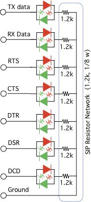
What's inside your average tracer? As described above, there is usually an LED, connected to each of the signal leads being monitored. There is usually a small resistor in series with the LED, to limit the current and reduce the signal voltage through the LED. (And, in a good tracer, there will be two LEDs on each lead, sharing a single resistor.) The to the right shows you a basic schematic for a "good" passive signal tracer. The resistor pack shown is XICOM Part number 265-1.2K (JAMECO part 276091), but they can also be 1/8-watt, 10% carbon-composition resistors. The value of 1.2k was determined by testing the LEDs I was using for good brightness at 12 volts DC, since some LEDs are brighter or darker at any given current. Some tracers will only monitor a couple leads, while some monitor the "Big Six" (TD, RD, RTS, CTS, DTR, and DSR), while others will include DCD, and even RI (Ring Indicator). Add the pin numbers for your favorite RS-232 interface... The LEDs here are reverse-polarity from each other. If the tracer uses bi-color LEDs, the schematic is basically the same, because the two-lead bi-color LED has the two LED components inside in this same reverse-polarity orientation. |
 |
|
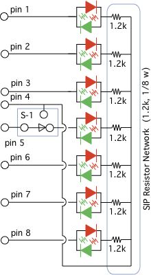
Make SURE you know where your signal ground is! This schematic is getting the common ground for the signals from pin 4 of the RJ-45 connector. If you are adapting the schematic for your own use, make sure you connect the common side of the resistors to the signal ground of your device! I've cobbled together an RJ-45 tracer, for use with Cisco, Cyclades, Xyplex (iTouch, MRV) and others. The main reliance is that the signal ground is on pin 4 of the RJ-45, and a switch is used to connect ground to pin 5 for use with Cisco devices. The modified schematic is shown to the right, and includes a switch (S-1). The pins are labeled for the RJ-45 pins. The switch I picked was a DPDT DIP switch, just because of the form factor (about as wide as the LEDs, and could be mounted flush with the case, so that the switch handle doesn't get broken off)
The first prototype worked well, but I couldn't find a small cable interconnect to use. (Consider how thin the device could be if I wanted to solder the RJ-45 cables to the board!) |
 |
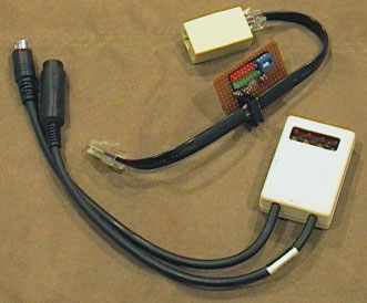
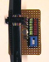
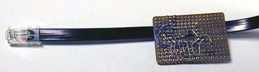
The pictures below show the first prototype, on perf-board, and hand-soldered. You can see how well the DIP switch lined up vertically with the LEDs, and you can also see the density of these 'oval' ROHM LEDs.
|
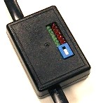
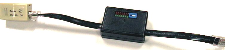
Once the first prototype passed the initial testing in service, I decided to make the second prototype, raising the LEDs and the switch to extend up to be flush with the case (due to the height of the insulation-displacement connector I had picked for the cable connection). With the RJ-45 cable as a pass-through, you can plug the tracer easily into RJ-45 adapters, or into connections on the Console Servers or RJ-45 patch panels. The switch sits flush with the case, and should not be easily changed 'by accident'. The LEDs are protected from pressure by the case, and the case is also holding the cable interconnect on its pins (preventing the connector from coming loose). The pigtail cable soming from either end makes it easy to add an RJ-45 cable coupler. This helps to protect the RJ-45 connectors when it's not in use, and also makes it easy to add the tracer in-line easily for quick monitoring of active consoles. |
  |
|
|
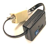
The image to the left shows the first prototype, next to an old tracer I built to monitor RS-232 signals using the Mini-DIN-8 connector used on Apple Macintosh (and SGI) computers.) The size of the case used on the Mac tracer was similar in size to the box used for the second RJ-45 prototype, as an example of the scale in the photo. The Mac only has one pair of in/out control leads, besides the TD/RD pair. This allows for either Flow Control or hardware handshaking, but not both (which is why there are only 4 pairs of LEDs). I found an in-line female Mini-DIN-8 connector, so I used that on the cable, instead of building a board- or chassis-mounted connector into the case (to keep the case size small). |
Here are some examples of the signal indications that are commonly seen, using the DataTran tracers.
DB-25 Signal Patterns
|
|
|
|
|
DB-9 Signal Patterns
|
|
|
|
|
Mixed DB-9 and DB-25 Signal Patterns
|
|
|
|
|
You can use a DB-25 adapter with a passive signal tracer to check the signals on RJ-45 signals (left), DB-9 devices (center), and other DB-25 devices (right), using the proper adapters. (Make sure that the RJ-45 wiring schema is the same for all of the adapters, and for testing the RJ-45 case you must be sure that the adapter on the tracer has the same RJ-45 schema as the device being checked.)
|
|
|
|
An unconnected tracer (left), and the tracer connected to a DTE device
(right)
|
|
A tracer connected to a DCE device
|
|
A tracer connected to another DCE device (left), and a DB-9 DataTran tracer
(right)
|
|
|
NOTICE: Most of the pages, articles, and tutorials on this website are copyrighted works. You may make 'deep links' to various pages. (If you let me know which page(s) you are linking to, I'll let you know if I move the page(s) during updates.) Please send me email if you wish to republish any material, or use it on your own website. |